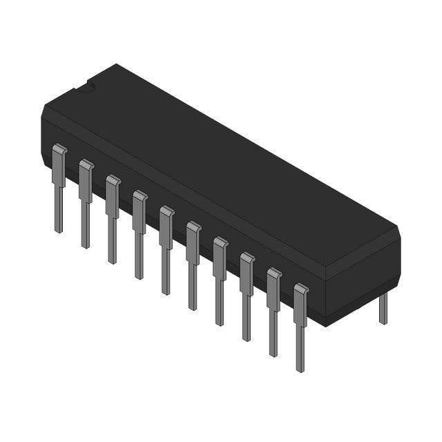
The CDC204DWR is a clock distribution and signal buffering integrated circuit from Texas Instruments. It belongs to the CDC family of clock drivers and is implemented as a hex inverter/clock driver intended for high-speed clock distribution applications. The device is designed to receive a digital clock signal and provide multiple buffered clock outputs with low propagation delay and sufficient drive capability to support distributed clock networks. It is commonly used in systems where a single clock source must drive multiple loads while maintaining signal integrity and minimizing timing degradation. The DWR suffix identifies the surface-mount SOIC package supplied in tape-and-reel format for automated assembly processes.
## Device Function and Positioning
The CDC204DWR is classified as a CMOS clock driver and clock distribution device. Internally, it incorporates six inverter-based driver channels that operate as high-speed clock buffers. The primary purpose of the device is to increase clock fanout capability by replicating and driving clock signals to multiple destinations within a digital system. Unlike phase-locked loop clock generators or clock synthesizers, the CDC204DWR does not generate new clock frequencies but performs clock buffering and distribution while preserving the frequency characteristics of the input signal. The architecture is optimized for digital clock networks used in microprocessor systems, memory subsystems, communication equipment, and other synchronous digital designs. By providing multiple buffered outputs from a common source, the device reduces the loading presented to the original clock generator and improves overall clock signal quality throughout the system.
## Electrical and Functional Parameters
The CDC204DWR operates from a nominal 5 V power supply, with a specified operating supply voltage range of 4.75 V to 5.25 V. Implemented using CMOS technology, the device enables low static power consumption while maintaining high-speed switching performance. It provides six output channels, each capable of driving relatively high capacitive loads. The input and output logic levels are CMOS compatible, ensuring seamless integration with standard digital logic systems. The maximum input frequency is specified at 80 MHz, allowing support for a wide range of microprocessor, memory, and communication subsystem clocks. The typical propagation delay is approximately 5.7 ns, which is critical for applications requiring low-skew clock distribution. Each output is capable of driving capacitive loads up to 50 pF, with a maximum low-level output current of 24 mA, providing sufficient drive strength for multiple clock destinations and PCB trace loading.
## Package and Mechanical Characteristics
The CDC204DWR is supplied in a 20-pin SOIC package suitable for surface-mount assembly. The gull-wing lead construction conforms to standard dual-row small-outline packaging practices, with approximate dimensions of 12.8 mm in length and 7.5 mm in width. The DWR packaging option denotes tape-and-reel configuration for automated production environments. The device’s package supports sufficient thermal dissipation for high-frequency clock distribution operations and is compatible with standard industrial PCB manufacturing processes.
## Signal Integrity and Clock Distribution Characteristics
The CDC204DWR is designed to maintain clock signal integrity across multiple destinations. Clock signals are sensitive to capacitive loading, trace impedance variations, and excessive fanout. The device mitigates these issues by isolating the original clock source from downstream loads through dedicated buffering stages. The inverter-based output architecture allows rapid transition times and reduced edge degradation, while the low propagation delay ensures synchronization accuracy. By distributing buffered clock outputs rather than directly connecting multiple loads to a clock oscillator, system designers can reduce timing skew and improve overall timing consistency.
## Operating Conditions
The device is intended to operate from a regulated 5 V supply and within a commercial temperature range up to 70°C. Proper PCB layout and power supply decoupling are required to maximize performance and maintain output drive strength. Placement near clock loads and implementation of low-impedance power distribution networks are recommended to minimize voltage droop and preserve timing integrity during high-speed operation.
## Typical Application Scenarios
The CDC204DWR is used in applications requiring distribution of a single clock source to multiple synchronous devices. Typical use cases include microprocessor-based systems where a single oscillator drives CPUs, memory devices, and peripheral controllers. The device is also suitable for telecommunications equipment, data acquisition systems, digital instrumentation, industrial control electronics, and embedded computing platforms. In memory subsystems, it can distribute clock signals to multiple memory devices while maintaining timing consistency. In communication systems, it functions as a clock fanout buffer for network controllers, interface devices, and protocol-processing hardware. It is equally applicable in digital test equipment and measurement instruments requiring synchronized clock delivery to multiple functional blocks.
## Conclusion
The CDC204DWR is a 5 V CMOS hex inverter/clock driver optimized for high-speed clock distribution and fanout applications. It provides six buffered clock outputs, supports clock frequencies up to 80 MHz, operates over a 4.75 V to 5.25 V supply range, and exhibits a typical propagation delay of 5.7 ns. Packaged in a 20-pin SOIC format, the device enables effective clock distribution across synchronous digital systems while minimizing source loading and preserving signal integrity. Its combination of high-speed operation, strong output drive capability, and dedicated buffering makes it suitable for a wide range of digital clock distribution architectures.